24-846_PAA Analysis (Jan 22) (Public).pdf (available for download)
INTRODUCTION
The Joint Multinational Readiness Center (JMRC) is the premier combined-arms training facility supporting the United States Army in Europe and Africa’s (USAREUR-AF) combat readiness. Success at JMRC requires rotational units (RTU) to use North Atlantic Treaty Organization (NATO) doctrine to defeat a world-class opposing force (OPFOR) in severely restricted terrain. To drive RTU readiness, JMRC replicates the acute threat observed in the European theater by combining TC 7-100 series publications with observations made in the wake of the Russian invasions of Ukrainian territory in 2014, 2019, and 2022.
JMRC’s OPFOR challenges the RTU in large-scale combat operations (LSCO) and seeks to render the field artillery battalion (FA BN) ineffective. During exercises, battalion (BN) and brigade (BDE) staffs frequently fail to accomplish detailed terrain analysis. Because of this, staffs fail to provide appropriate inputs to the FA BN commander and the BDE commander during the military decisionmaking process (MDMP). Failure to describe the terrain in the BDE’s area of operations presents risk to mission accomplishment in the face of an experienced OPFOR.
Led by the BDE and BN intelligence sections, one of the most important contributions staffs provide to mission planning is terrain analysis supporting the identification of suitable position areas for artillery (PAA). For the most effective units, intelligence warfighters’ integrating processes producing a complete picture of the operational environment (OE) inform this selection. If intelligence warfighters fail to provide understanding of the terrain, the FA BN commander and BDE commander will lack critical information and are less likely to make optimal decisions in pursuit of mission accomplishment. In a worst-case scenario, the FA BN would not be able to direct fires, lack the ability to execute sufficient survivability movements in the face of counter- fire, and assume risk in providing sustainment to the BN.
This document is meant for two audiences: military intelligence (MI) officers that support artillery units, and the leadership of artillery units who seek to effectively use MI capabilities to augment their unit’s effectiveness.
This document will do two things: First, it will explain how to execute terrain analysis and make insightful PAA site recommendations in support of the FA BN commander’s mission; Second, it will demonstrate how to implement this conceptual process using the current hardware and software available to warfighters in the MI programs of record. The authors of this document used ArcPRO—the geospatial information system (GIS) software present on the geospatial intelligence workstation (GWS) and the best means of producing such analysis at the BDE echelon. This document will not review core 35G and 12Y tasks that support this conceptual process.
This document is a case study for PAA site selection in severely restricted terrain in the European theater. The process and considerations detailed here can (with judicial adjustment) be adapted to any fight and any theater in the world with severely restricted terrain. The end state of this document is to provide field artillery (FA) units preparing for or operating in severely restricted terrain with a more comprehensive understanding of the planning considerations necessary to be successful in combat.
METHODOLOGY
This document has four sections: First, this document identifies the capabilities and limitations of the U.S. Paladin M1097A7 155mm howitzer and the Russian 2S19 152mm howitzer. The document suggests criteria for PAA site selection from the capabilities and doctrine of both platforms. Second, this document provides an overview of the terrain within the Hohenfels Training Area (HTA) and Maneuver Rights Area (MRA). Third, it applies the criteria to case points on the terrain to determine the most favorable PAA locations. Fourth, to complement the previous sections, the document focuses on the science of PAA site selection. This section also discusses the art of PAA site selection from the table of PAA site possibilities. This discussion includes factors that terrain models cannot quantify. The document concludes with an assessment of many suitable PAA locations in the HTA and MRA to which a staff can apply their mission variables and make recommendations to their commander.
Two assumptions are necessary to frame this analysis. These assumptions are viable considering that their conditions hold true for most multinational exercises that occur at JMRC: First, the exercise design is West-to-East oriented. This means that the RTU will occupy PAAs in the West and OPFOR will occupy PAAs in the East. Second, the RTU’s adjacent (constructive) BDEs will have no effect on the organic FA BN mission. This assumption is necessary to avoid cross-boundary fires in conjunction with a wide array of simulated NATO partners.
CAPABILITIES AND LIMITATIONS
The M109A7 Paladin (See Figure 1) is a self-propelled 155mm howitzer equipped with an M284 cannon. The Paladin has a maximum firing range of 30km for standard munitions and a maximum firing rate of four rounds per minute for three minutes or one round per minute sustained. The Paladin possesses global positioning satellite (GPS) navigation and other tools that provide approximate current positioning from the last known GPS position to assist with precision fires.

With its 675hp engine (325hp less than its Russian peer, the 2S19), the Paladin has a max speed over level ground of 61kph and a travel range of 300 kilometers. The Paladin is expected to execute an emergency occupation in 75 seconds, with a general occupation requirement of 3 minutes. At 38,000 kg, the Paladin is at a mobility disadvantage compared to the 2S19 since it is almost as heavy as the 2S19, which weighs 39,000 kg, but with a less powerful engine. The standard Paladin combat load includes 42 stored projectiles and 31 propellant canisters. BNs consist of 18 howitzers evenly split between three Batteries. The Paladin thrives in its ability to quickly emplace and displace using its internal navigation system combined with its Paladin digital fire control system. The Paladin, usually controlled by a platoon or battery fire direction center (FDC), can internally compute firing data and connect with a secondary artillery command and control system to execute technical fire direction.
U.S. and NATO doctrine prescribe that field artillery forces apply firepower to support the maneuver commander. U.S. fire support doctrine states that “the commander employs these capabilities to support the scheme of maneuver, to mass firepower, and to destroy, neutralize, and suppress enemy forces.” U.S. doctrine further supplements this broad definition by defining the four fire support functions as:
- Support forces in contact
- Support the concept of operations
- Synchronize and converge lethal and nonlethal fire support across all domains
- Sustain and protect the fire support system
Paladin employment follows one of three models: platoon, paired, or single howitzer methods. Smaller firing elements provide increased survivability, but create challenges to command and sustain. Platoon employment is generally preferred; however, commander’s guidance and mission variables will dictate the method of employment to balance command, control, and sustainment considerations. After occupation of a primary or alternate PAA, the Paladin battery is capable of numerous dispersion techniques. The most common in a contested environment and most commonly observed at JMRC is terrain gun positioning. This occurs when units place guns within a tree line that provides a degree of horizontal and vertical concealment. However, other dispersion techniques like the platoon wedge, battery star, battery line, and battery lazy-w are also applicable depending on mission variables.

Priority #1. No more than 90 mils (5 degrees) of ground slope: Ground slope must be the primary planning factor for the M109A7 howitzer. A Paladin should not exceed 90 mils or five degrees of cant (ground slope) at any time because this prevents accurate fires. This presents rotational units with constrained opportunities for PAA occupation because 60 percent of HTA has a ground slope beyond this limitation.
Priority #2. Supports unit communications plan: The distances inherent to the most favorable FA operations challenge unit communications plans. Applied to this training area, communication is exceptionally more challenging and requires a detailed communications plan. The S-6 (or, secondarily, the S-2) must conduct a viewshed analysis on all potential PAA locations during the planning process to anticipate communications issues.
Priority #3. Battery PAAs with dimensions 3km x 3km: FM 3-09 states, “The exact size of a position area for artillery depends on the mission variables of mission, enemy, terrain and weather, troops, and support available, time available, and civil considerations (METT-TC). As a rule of thumb, a Paladin platoon normally requires a position area for artillery encompassing over four square kilometers.” ATP 3-09.70 concurs that, “The Paladin platoon PAA may require an area approximately 1,500 by 3,000 meters (more than 4 square kilometers). A platoon position of this size provides two firing areas with multiple locations for howitzer emplacement.” Put two platoons side-by-side and this results in a 3km x 3km battery PAA. HTA does not have large open or flat areas to plan for artillery positions. Units must be prepared to adapt to irregular PAA sizes that fit between terrain features and highly restrictive terrain. Units must also consider the possibility of clustering smaller areas into large PAAs. This allows for more flexibility in planning and can provide additional space for batteries to maneuver.
Priority #4. Presence of tree lines that provide cover and concealment: Survivability is critical, and to that end the terrain in HTA offers ideal conditions for Paladin hide sites. The FA BN staff should plan to use HTA’s tree lines and vegetation to the unit’s advantage. HTA does possess some select hide sites without restricted terrain and excellent concealment from enemy observation posts and aerial observers.
Priority #5. Absence of populated areas, distance from heavily trafficked roads: German citizens, role-players, and OPFOR occupy villages in the training area during exercises. The FA BN should avoid these areas at all costs. The towns’ occupants are mercurial, always liable to change behavior in response to levels of trust and stability generated by the RTU during the exercise. Any element that occupies near or drives through these areas should consider itself under surveillance. Further, the enemy maintains a capable special purpose force (SPF) that uses civilian vehicles to conduct reconnaissance along HTA’s roadways. FA BN elements visible from major roadways increase their exposure to enemy direct and indirect fires (IDF).
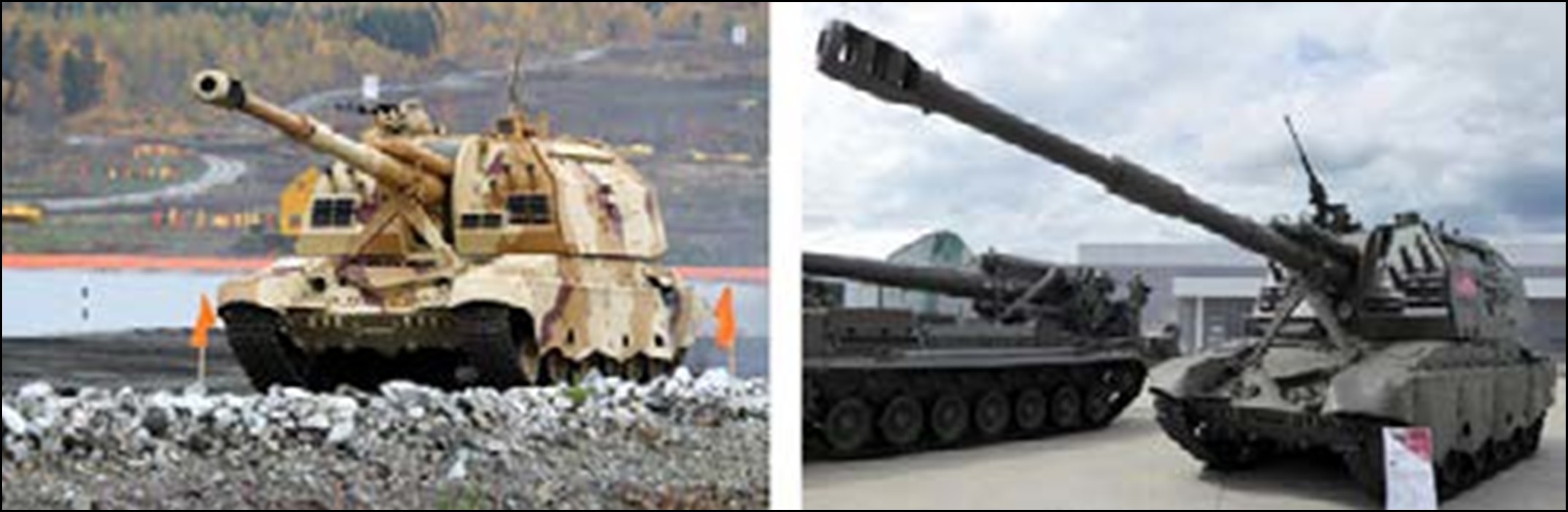
The 2S19M2 (See Figure 2, afterward referred to as the 2S19) is the most advanced edition of Russia’s flagship self-propelled artillery platform for motorized and mechanized brigade tactical groups (BTG). The 2S19 has a fully digital fire-control system with digital electronic maps and globalnaya navigatsionnaya sputnikovaya sistema (GLONASS) navigation that can receive targeting guidance from unmanned aerial vehicle (UAV) platforms. The engine capacity is greater than previous versions at 1,000 horsepower (the same as the T-90 main battle tank), reducing occupation time to 30 to 90 seconds (depending on the source) with commensurate theoretical but unverified improvements in its displacement time. U.S. Army Training and Doctrine Command (TRADOC) G-2’s Threat Analysis Directorate assesses emplacement times from 3:35 to 5:00 minutes and displacement times from 2:20 minutes. The M2-edition also adds an auto-loader for all standard Russian 152mm munitions, improving reliability and the sustained firing rate of its 50-round basic load for up to 8 rounds per minute.
It is difficult to more concisely explain how OPFOR sees artillery than in Chapter 7, FM 7-100.1, Opposing Force Operations. “[OPFOR] views itself as using various forms of fire support to achieve success during offensive and defensive operations. In the offense, fire support is important to the success of any attack. It can destroy key systems; disrupt, immobilize, or destroy enemy groupings; and repel counter attacks. Fire support is also the cornerstone of any defense, blunting attacks at the crucial point in the battle. It disrupts enemy preparations for the attack, causes attrition as he approaches, and repels forces.”
Doctrinally, OPFOR uses 2S19s for four purposes in LSCO:
- Support to offense
- Support to defense
- Disruption
- Support to information warfare (IW)
In all forms of OPFOR offense and defense, 2S19s typically execute suppressive artillery fires and obscuration missions using smoke as part of the assault force. Disruption forces have no set composition according to FM 7-100.1, yet may contain artillery systems depending on the effects the OPFOR commander seeks to apply.
“Two factors govern the deployment of IDF support units: continuity [of fires] and dispersion.” OPFOR designates three kinds of PAA—primary, alternate, and temporary. Primary and alternate PAAs are familiar concepts to U.S. forces. However, the temporary PAA that OPFOR designates for the execution of a particular fire mission and vacates upon completion of that mission. OPFOR is also capable of several tactics like split-battery and dispersed platoon tactics, which increase the survivability of OPFOR fire support assets.

Priority #1. No more than 90 mils (5 degrees) of ground slope: No Change. Priority #2. Supports unit communications plan: No Change.
Priority #3. Battery PAAs with dimensions 3km x 3km; Platoon PAAs 1km x 1km: The OPFOR employment criteria allow flexibility in employment methods to balance the continuity of fires and risk to the guns. During the exercise, OPFOR position each platoon 500m distanced from the other, allowing the battery commander to increase survivability and decrease the chance of effective RTU counter-fire.
Priority #4. Presence of tree lines that provide cover and concealment: No Change.
Priority #5. Proximity to urban cover: The MRA is comprised of several established towns and small villages. Elements of the OPFOR artillery use these areas as hide sites and firing. While these areas may be under RTU surveillance, the collateral damage estimation forced upon the RTU and most RTUs’ risk–averse posture allows for greater survivability of OPFOR guns.

The geographic scope of the study is the Hohenfels Training Area (HTA) (See Figure 3) and the Maneuver Rights Area (MRA)—an area surrounding the boundary of the HTA that plays host to OPFOR’s constructive artillery systems. HTA restricts the boundaries of the RTU’s PAAs, resulting in a 15-kilometer tall by 20-kilometer wide area for RTU PAA site consideration. As of September 2023, RTUs may now request permission to establish PAAs in the portion of the MRA to the West of HTA’s formal boundaries, however, this is a recent development and there is not sufficient data to support analysis of those PAAs at the time of publication. However, because of battlefield geometry, the RTU’s artillery assets rarely occupy terrain east of the 04 Easting, which bisects HTA into western and eastern halves.
While HTA is small compared to other U.S. Combat Training Center (CTC) standards, the MRA around HTA is vast. In most exercises, a constructive OPFOR division occupies the MRA. However, enemy artillery only use one section of the MRA on the East side of HTA measuring 13km x 21km for PAAs relevant to this study. It is bounded in the West by HTA’s eastern boundary, in the East by Highway A93, in the North by the 61 Northing, and in the South by the 40 Northing.
HTA lends itself to analysis using the “avenue-in-depth” technique described in ATP 2-01.3. HTA has three conceptual areas that or “corridors” to match the current parlance at other CTCs—the Northern, Central, and Southern Corridors (See Figure 4).
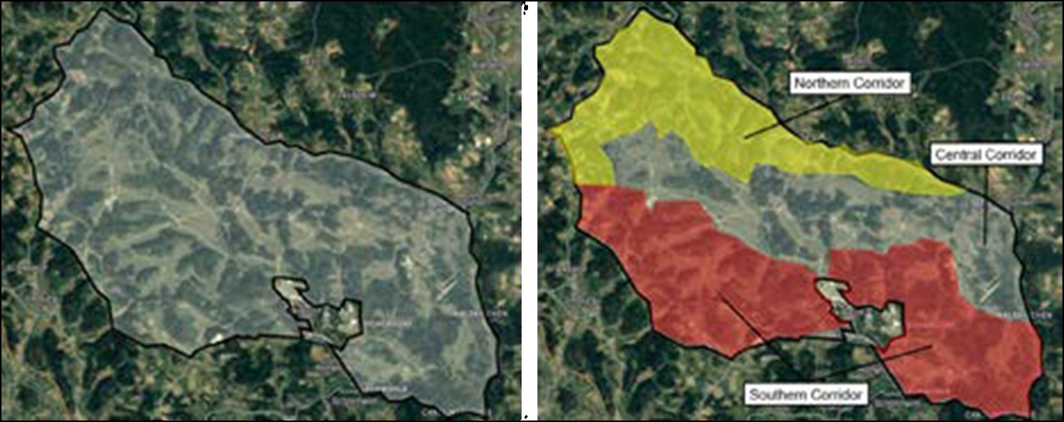
Moving from West to East, HTA’s northern corridor becomes narrower and flatter, loses its forestation, and merges with the central corridor. The Northern corridor only has one west-east oriented road that splits the corridor into two halves. Along its entire length, secondary perpendicular roads lead north to the HTA boundary and south into the Central corridor. The Northern corridor is densely forested with dispersed pockets of sloped clearings. Forestation provides artillery platforms cover from rapid maneuver incursion and concealment from aerial and ground observation. The dispersed clearings offer multiple opportunities for RTU maneuver forces to establish defenses in wood lines and engage the opposing dismounted maneuver. The Northern corridor’s terrain is undulating— characterized by many prominent hills that create rapid elevation changes and steeper slopes than those found elsewhere in the training area. The absence of urban areas populated by civilians in the Northern corridor means that it can also provide better operational security (OPSEC) and freedom of movement. The Northern corridor favors the defending force and also favors the artillery that holds the terrain—forestation and hills make inbound artillery shells significantly less effective; however, the occupying party also suffers from less maneuverable terrain, and PAAs are smaller than are desirable.
HTA’s Central corridor spans the width of the installation and is less forested than the Northern or Southern corridors. The Central corridor also has a higher density of unimproved and improved roads than the other corridors. In combination, this makes the Central corridor the most suitable area for rapid offensive maneuver. It has large swaths of land that are within the ground slope constraints for artillery platforms, making it an attractive, though risky, area for establishing PAAs. The multiple town sets in the Central corridor make it extremely difficult to maintain operations security (OPSEC) and circumventing them increases planning estimates for movement times. The Central corridor favors the attacker by the grace of the wide mobility corridors and the plethora of navigable roads that support rapid maneuver capabilities. It does, however, have key terrain that, if controlled by the defender, severely impede offensive action.
HTA’s Southern corridor’s most crucial characteristic is that it splits the Hohenfels cantonment area, meaning any maneuver threat to PAAs in the Southern corridor must first transit the Central corridor and turn south again. The Southern corridor is lightly wooded and has many north-south oriented roads that connect it to the Central corridor through a screen of forested hills. A single west-east road connects all the other roads but ultimately leads to the cantonment area, which is out of bounds for operations. Solely from terrain considerations, the eastern side of the Southern corridor has the best terrain in HTA for artillery. It has forested areas but with broad flat areas for PAAs. HTA controls maneuver access to this part of the training area through two secondary roads that are definitively within the defender’s control. The Southern corridor favors the defender on each side of the cantonment area.
The MRA, on the other hand, has many urban population centers, high-speed avenues of approach, and extensive logistics infrastructure. These factors increase the lethality of OPFOR fire support assets and permit the (notional, and for simulation purposes only) exploitation of urban terrain as concealment against observation and cover against RTU counter-fire missions. An active north- south river splits the area. However, there are many bridges capable of supporting self-propelled artillery movement. As a heuristic judgment, the MRA appears to have more land fit for occupation by artillery platforms by a percentage of the total area. The MRA provides OPFOR with ideal conditions to execute fire support missions with a mixture of cover and concealment types and relatively unfluctuating ground slope, increasing the potential options for PAA site selection.
DATA SETS
Topological Base map. Source: Bundesvermessungsamt (BEV) (German Ministry for Surveyorship).
SRTM. Source: Likely National Geospatial Agency (NGA) or United States Geological Survey (U.S.G.S.) legacy data in Integrated Training Area Management (ITAM) archives. Note: SRTM is the standard military issue elevation data that underpins ground slope and site-to-crest analysis.
HTA Boundary Layer. Source: JMRC ITAM.
Roads Layer. Source: Open Street Map (OSM).
Urban Area Layer. Source: Unknown, legacy file in ITAM archives.
Military Range Layer (exercise town sets). Source: JMRC ITAM.
Woodland Layer. Source: JMRC Department of Public Works (suspected, though not confirmed) Waterways Layer. Source: Open Street Map. Note: 50m blue buffer added by JMRC ITAM Table 3 displays case points used in this study.

APPLY CRITERIA TO THE TERRAIN
Open the base layer in ArcPRO. The base layer is preferably topographic. Next, load digital terrain evaluation data (DTED) (acquirable through 12Y and 35G channels, ultimately from the Army Corps of Engineers, NGA, or U.S.G.S.) as the foundation for all terrain analysis to follow.
Add the remaining layers, which contain operational graphics and modified combined obstacle overlay (MCOO) elements; HTA boundary layer, roads layer, urban area layer, military ranges layer, woodland layer, and waterways layer. As an administrative note, layers may need to be turned off to reduce the workload on the hardware.
Case Point #14, Horse’s Head, is used throughout the remainder of the document (See Figure 5).

Priority #1. No more than 90 mils (5 degrees) of ground slope: Using the loaded DTED data, execute ground slope analysis. Although the ground slope bands appropriate for this analysis are the result of unit SOP and commander’s preference, three bands are common:
- 0 to 2.5 degrees displayed as transparent
- 2.5 degrees to 5 degrees displayed as amber
- 5 degrees or more displayed as red (See Figure 9).

As an example, assume that the FA BN staff is considering placing a PAA in the area marked in Figure 5, colloquially identified as “Horse’s Head” by the JMRC community. The ground slope analysis displayed in Figure 6 confirms that the terrain’s slope is suitable throughout the clearing for gun emplacement. This area supports Priority #1.
Priority #2. Supports unit communications plan: Using the already loaded data, execute a viewshed analysis to see how supportive the area is to a communications plan. (The S-6 can also perform this using a program called “SPEED”). Set the height to 10 meters to approximate the height of an OE-254 antenna (See Figure 7).

While derived from quantitative data, the judgment of whether this PAA site supports the unit communications plan is collaborative and the product of unit MTOE, limitations, and constraints. An invaluable tactic, technique, and procedure (TTP) that the field artillery observer, coach, trainer (OC/T) team at JMRC has observed is to integrate templated BDE re-transmission (RX) sites into the FA BN RX plan.
In this case, Horse’s Head supports channeling communications outside its immediate vicinity to adjacent terrain features, albeit only in one direction. It moderately fulfills priority #2.
Priority #3. Battery PAAs with dimensions 3km x 3km: All standard NATO military maps use the military grid reference system (MGRS), which is a reliable marker to judge potential PAA size. (See Figure 6). The rule of thumb offered by FM 3-09 is 3km x 3km dimensions for Paladin battery PAAs. However, HTA is so heavily forested that PAAs of the recommended size are impossible. By default, then, all the case points this document presents, including Horse’s Head, will ultimately fail Priority #3, but that does not mean the area is unsuitable for occupation—it simply means that a commander may apply decision-criteria regarding the risk of using such an area.
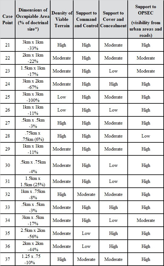
In Table 4 at the end of this section—rather than “fail” all case points on Priority #3—provides the approximate ratio of the “area surrounding a case point suitable for occupation” to “desired PAA size” to help S-2s appropriately communicate risk. In this case, the Horse’s Head PAA is about 4.16 percent of the occupiable area recommended by FM 3-09.
Priority #4. Presence of tree lines that provide cover and concealment: There are two sides to the coin. On one side, PAA size is heavily restricted by forestation. On the other, the near omnipresence of forestation provides a plethora of potential hide sites that can reasonably provide both horizontal and vertical cover and concealment. In the case of the Horse’s Head, tree lines are adequate to provide cover and concealment to RTU artillery platforms, satisfying Priority #4.
Priority #5: Absence of populated areas: As previously mentioned, the town sets operated by HTA’s OE team interact with the battlefield, the friendly RTU, and the OPFOR. The civilians in these town sets record military movements. Local media outlets approach military forces and confront them about their actions using leading questions with a pre-determined bias for or against friendly forces. The RTU should treat urban areas as an object of extreme reticence and avoid them at all costs. The town sets are unpredictable and often result in OPSEC compromises that leak onto JMRC’s simulated social media “Information Operations Network” (ION) and are subsequently discovered by the OPFOR and used for targeting.

Second, proximity to roads and visibility from commonly trafficked roads make PAAs liable to discovery and reporting by traveling civilians, special purpose forces (SPF), and the Donovian defense league (DDL), an irregular paramilitary force that cooperates with the OPFOR. As mobile as Paladins may be, the time required to displace the guns, the FDC, and the associated vehicles and equipment results in bringing guns offline for an amount of time before returning to an in- position, ready to fire (IPRTF) status. PAAs that are not visible from roads provide a considerable advantage to OPSEC.
In this case, it is impossible to travel to/from the Horse’s Head without civilian observation (See Figure 8, annotated). However, units can reduce risk by using secondary roads or off-road travel. The roads near the PAA are seldom trafficked by civilians, providing a modicum of OPSEC support. Firing from the Horse’s Head is unlikely to result in an OPFOR counter-fire that harms civilian casualties because it is about 1km from the PAA. In this case, the Horse’s Head presents a moderate risk related to the presence of an urban area for Priority #5.
RESULTS
The five quantifiable criteria are by design, unchanging. They rely on immutable elements of HTA no matter the unit mission, OPFOR mission, and exercise design. To that end, this document compiles the results of the 20 case points considered for the RTU in Table 4. In all columns, a high value represents low risk. In contrast, a low value should indicate high rates of risk.

Using the process described above, 2S19 criteria established earlier can be used to perform the same analysis regarding the risks inherent to the OPFOR’s choice of PAAs in the MRA. It is important to note that while OPFOR strives to consider the conditions on the battlefield and make appropriate decisions, there are inherent discrepancies between how to use constructive (simulated) artillery in the MRA and how units use artillery in identical live circumstances.
This quantitative analysis is foundational to staffs, specifically S-2s, who seek to understand and convey effects to mission success. However, it is not the only information worth considering.
COMMENTARY ON THE ART
This section covers some of the qualitative information that is equally important in the discussion of the art of PAA site selection. The art of PAA site selection is divided into two parts: intelligence considerations and operations considerations.
Intelligence Considerations
Position of Enemy Artillery. Perhaps the most critical factors for PAA site selection that this analysis does not quantitatively integrate are the position and capabilities of the OPFOR, which would present risk to the RTU’s fire support assets. S-2s should execute the analysis described here, template enemy positions with their range rings, then factor enemy artillery reach into PAA site recommendations.
Weather. Excluded from this quantitative assessment are the exigent weather conditions that shape the terrain’s effect on combat operations. Unimproved roads leading away from improved roads are highly susceptible to degrading weather effects. HTA is notably absent of water features but still consists of several low-lying areas with a high underground water line. The ground turns into a clay bog during runs of precipitation. The soft soil absorbs the precipitation with little runoff and creates hazards to the efficient and safe execution of FA operations.
Road Integrity. Road load capacity is a factor not quantified in this analysis, though such information is available. All improved roads throughout the training area can support the movement of the heaviest wheeled and tracked vehicles. However, not all roads are of suitable incline to permit travel, especially after inclement weather conditions that further degrade unimproved roads essential to PAA emplacement and displacement. JMRC’s integrated training area management (ITAM) team analysis suggests that 50.3 percent of HTA has an incline of more than 10 percent. While not an explicit problem for self-propelled artillery under ideal conditions, planners may reconsider the risk and the estimated movement and maneuver times for such assets. For towed artillery, inclines of more than 10 percent prohibit towing and greatly restrict PAA site possibilities without extensive increases to movement timelines.
Communications. A PAA’s suitability partially depends on its ability to support the unit communications plan. Different radio systems use other forms of wave propagation to communicate and therefore have varying strengths and weaknesses. Suppose the unit uses high-frequency (HF) radios as their primary mode of communication, not the Army’s single channel ground and airborne radio system (SINCGARS) frequency modulation (FM) radio. In that case, the line-of- sight (LOS) viewshed is less critical in the S-2’s analysis of potential PAA site locations because HF radios operate using sky-waves unsusceptible to LOS issues, unlike the SINCGARS’ ground- wave propagation.
Operations Considerations
Division of Labor. Efficient PAA selection should be a clear division of labor between the RTU BN and BDE staffs. The BDE has the best co-location of expertise, hardware, and software to execute the initial terrain analysis to support PAA selection—which is explicitly regarded as the maneuver commander’s responsibility and often delegated to the BDE S-3 and BDE fire support officer (FSO).29 At the BDE echelon, the co-location of the BDE FSO and the BDE geospatial intelligence (GEOINT) cell (consisting of 35Gs and 12Ys and their GWS computer systems) have the necessary expertise to execute the digital analytical support to decision making. Because PAA selection decisions affect land management—a BDE S-3s responsibility—proximity to the BDE S-3 is an advantage for land de-confliction that balances land allocation to each of the RTU’s subordinate elements. Holding initial terrain analysis for PAA selection at the BDE level is most efficient, however, bottom-up feedback is still essential because the BN can take small sections of the larger analysis and dive deeper into the implications that the BDE’s selection has on field artillery operations.
On the other hand, attempts to delegate terrain analysis to the BN staff often results in ineffective support to commander’s understanding of the battlefield and decision making. BN staffs lack the modification table of organizational equipment (MTOE) to execute the demanding digital tasks required to perform terrain analysis and the personnel trained to execute them. The portable multi- function workstations (PMFWS) laptop issued to the BN does have a limited capacity to execute terrain analysis on small areas; however, attempts to analyze an entire BDE frontage for possible PAA sites are less precise than those executed at the BDE level.
Further, depending on the version of MTOE equipment issued to the unit, ArcPRO software is not present on all BN PMFWS’s. The most recent version, Capabilities Drop 2 (CD2), uses a Palantir software baseline that provides some, but not all the functionality that ArcPRO provides. BN staffs should use this limited capability to provide information and make recommendations to battery commanders on how they position their guns in the provided PAA.
In preparation for the eventual shift of responsibility for FA BNs to division artillery (DIVARTY) it is likely that terrain analysis supporting PAA site selection will receive greater emphasis than under a maneuver BDE. Greater emphasis by leaders—paired with the technical competence and fires expertise in the DIVARTY S-2—will provide specialized treatment for artillery units because the DIVARTY S-2 will not suffer from the competing priorities endemic to a maneuver BDE S-2 engaged in combat operations.

Battlespace Management. Units that fight in HTA struggle to manage land precisely enough to coordinate and deconflict land. Because artillery positions in the rear area, deconfliction between fires, sustainment, and C2 areas is vital to providing responsive and accurate fires to support maneuver. For the same reasons that artillery must manage risk because of the severely restricted terrain, planners must consider the effect that severely restricted terrain has on the unit’s ability to maintain ideal dispersion and deconfliction across the battlespace. When conducting MDMP, teams must hold land management at a premium during the planning process. For their part, when designating locations for PAAs, artillery units must use viewshed analysis, slope analysis, and imagery at a minimum, while true site reconnaissance is the gold standard.
Non-Standard PAAs. The restrictive nature of HTA only permits irregular PAAs, typically 1km by 1km or less, and clustered in smaller contingent areas, forcing the staff to mitigate risk by building primary and alternate locations. Poor integration between the S-2, S-3, S-6, and fire direction officer (FDO) results in unnecessary hardship for artillery teams.
PAA Site Selection Trends. Preferably, units should array PAAs evenly throughout the western side of the box, moving east towards the 03 easting throughout the operation as conditions dictate. This progression would connect multiple RX locations to provide communication throughout the breadth of the box. Most often, planners build PAAs in the Northern corridor of HTA, where more open pockets of terrain are available. A more extensive network of unimproved roads allows for a greater variety of hide sites and firing point locations. Because of this, RTUs typically continually rotate back to previously used PAAs even after receipt of accurate enemy fires. For some units, this may be a deliberate decision, for others, it is the result of not sufficiently tracking PAA use. The Howitzer Tracking Chart (See Figure 11) described in ATP 3-09.70 Paladin Operations and ATP 3-09.50, Field Artillery Cannon Battery, is an effective tool that planners rarely use, but extremely effective at supporting PAA movement tracking. RTUs should minimize reusing PAAs, especially those where units previously received accurate IDF. OPFOR is known for using small reconnaissance teams of two to four personnel in hide sites to wait for artillery to reoccupy already burned-out PAAs.
Unfortunately, as discussed earlier, this area possesses extensive hill networks and can result in congestion, creating a large, centralized target for OPFOR reconnaissance and fires. This is especially the case because of the area’s altitude above the rest of HTA. For this reason, this area is also a favorite for BDE and BN command posts (CPs), causing several unit headquarters to occupy in close vicinity.
In contrast, roughly 20 percent of RTU PAAs reside in the Southern corridor. This area typically holds the brigade support battalion (BSB) and has the worst communication and terrain conditions in the training area, especially in the event of inclement weather. The most effective risk mitigation strategies are effective RX placement and leadership engagement to minimize vehicle mobility issues that require wrecker support. Additionally, the Southern corridor of HTA has fewer towns, which reduces the routes available in exchange for providing more ideal conditions for OPSEC.
Typically, units use non-standard PAA sizes and shapes in HTA. This issue stems from a combination of problems, primarily a unit’s inability to coordinate land in a small training area as well as the restrictive terrain. Additionally, the lack of a tested and versatile primary, alternate, contingency, and emergency (PACE) communications plans across the BDE adds to this unique problem set. Successful units consider communication constraints and convince the BDE to prioritize the fires net (digital or voice) on RX platforms outside the FA BN footprint. Viewshed analysis tools held at both the BDE and BN levels must be present in planning to minimize the risk to the digital sensor- to-shooter fight. Finally, the S-6 must be a prominent figure in the FA BN main command post (MCP), consistently providing insight into PAA development.
NOTES ON THE M777
While the focus in this document has been on self-propelled platforms, towed platforms deserve some explicit attention to the unique difficulties incurred when designating, occupying, and using PAA sites. The following are recommendations and an explanation of factors to consider for PAA site selection criteria for the M777.

Table 6. M777 evaluation criteria (Operations Group, Joint Multinational Readiness Center) VIEW ORIGINAL
Priority #1. No more than 90 mils (5 degrees) of ground slope: No change from M109A7. Priority #2:. Supports unit communications plan: No change from M109A7.
Priority #3. Battery PAAs with dimensions 2km x 2km: Per FM 3-09, “Units equipped with M119A3 or M777A2 require one square kilometer PAA.” Although not explicit in doctrine, the 1km x 1km description can only reasonably apply to a M777A2 platoon. Add an alternate PAA and the area required for a platoon is 1km x 2km. Put two platoons adjacent to each other to acquire the 2km x 2km total area required to house a survivable M777 battery. HTA and the MRA do not have large open or flat areas to plan for artillery positions. Limited positions near hide locations that can accommodate the M777 exist. Most locations that provide appropriate terrain to occupy the M777 are in open areas.
Priority #4. 10 degree change in slope when towing: The maximum recommended slope for an M777 is 10 degrees. This is an object of particular difficulty for the M777 because a 10 degree slope accounts for over 50.3 percent of HTA. Additionally, the uneven micro-terrain can create many pinch points that increase the risk to equipment when trying to navigate towed artillery.
Priority #5. Presence of tree lines that provide cover and concealment: Maneuvering within the tree line is extremely difficult with the limited turn radius and extended length of the howitzer- prime mover combination. When occupying in the wood line to provide cover and concealment, the M777 will be restricted in how well it can maneuver.
Priority #6. Absence of populated areas, distance from heavily trafficked roads: No change from M109A7.
CONCLUSION
HTA’s severely restricted terrain is exceptionally challenging for field artillery operations. The goal of this document has been to visualize and explain exactly how challenging it can be for commanders and staff to properly account for the effect severely restricted terrain has on the planning and execution of FA operations. This analysis has outlined the essential data required to understand HTA’s terrain and its effect on FA operations, then subsequently provided the conceptual tools to turn that data into information. Further, this document compiles the products of that conceptual analysis and provides meaning to each potential PAA site considered. Finally, this document discussed the art of PAA site selection, which goes beyond the data and interprets it considering qualitative factors.
Endnotes are included in the attached pdf file.
Additional Resources
Follow Us on Social Media:
Social Sharing