Pittsburgh District Weld Shop, Structural Design partner for money saving lifting device

By Kerry Brown, Crane Operator, Maintenance BranchMay 22, 2012

Lifting Device
1 / 6 Show Caption + Hide Caption – Employees of the Corps of Engineers, Pittsburgh District's Structural Design Section and Weld Shop at PEWARS designed and fabricated this lifting device for needle dams used during lock chamber dewaterings. The device consolidates 16 crane lifts into... (Photo Credit: U.S. Army) VIEW ORIGINAL
Needle Dam on Barge
2 / 6 Show Caption + Hide Caption – Employees of the Corps of Engineers, Pittsburgh District's Structural Design Section and Weld Shop at PEWARS designed and fabricated this lifting device for needle dams used during lock chamber dewaterings. The device consolidates 16 crane lifts into... (Photo Credit: U.S. Army) VIEW ORIGINAL
Lifting device in use
3 / 6 Show Caption + Hide Caption – Employees of the Corps of Engineers, Pittsburgh District's Structural Design Section and Weld Shop at PEWARS designed and fabricated this lifting device for needle dams used during lock chamber dewaterings. The device consolidates 16 crane lifts into... (Photo Credit: U.S. Army) VIEW ORIGINAL
Needle dam illustration
4 / 6 Show Caption + Hide Caption – (Photo Credit: U.S. Army) VIEW ORIGINAL
Needle dam installation 1
5 / 6 Show Caption + Hide Caption – (Photo Credit: U.S. Army) VIEW ORIGINAL
Needle dam installation 3
6 / 6 Show Caption + Hide Caption – (Photo Credit: U.S. Army) VIEW ORIGINAL

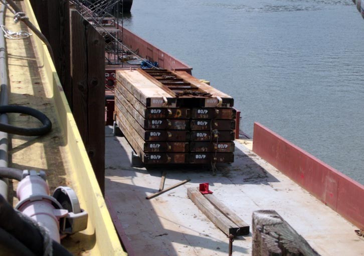
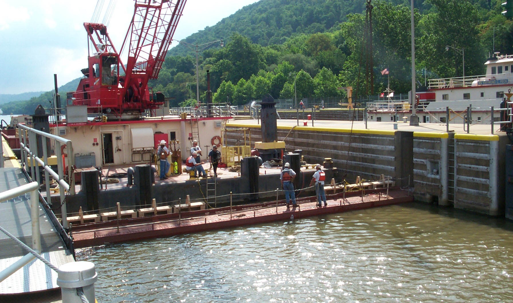
NEVILLE ISLAND, Pa. -- Pittsburgh Engineer Warehouse and Repair Shop (PEWARS) employees recently used a new lifting device to load a temporary dam into a barge for use during the upcoming lock chamber dewatering at Lock 4, Monongahela River.

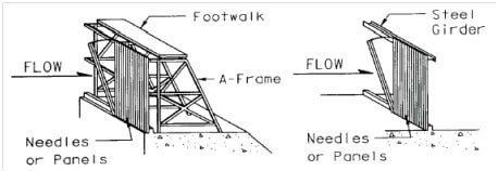
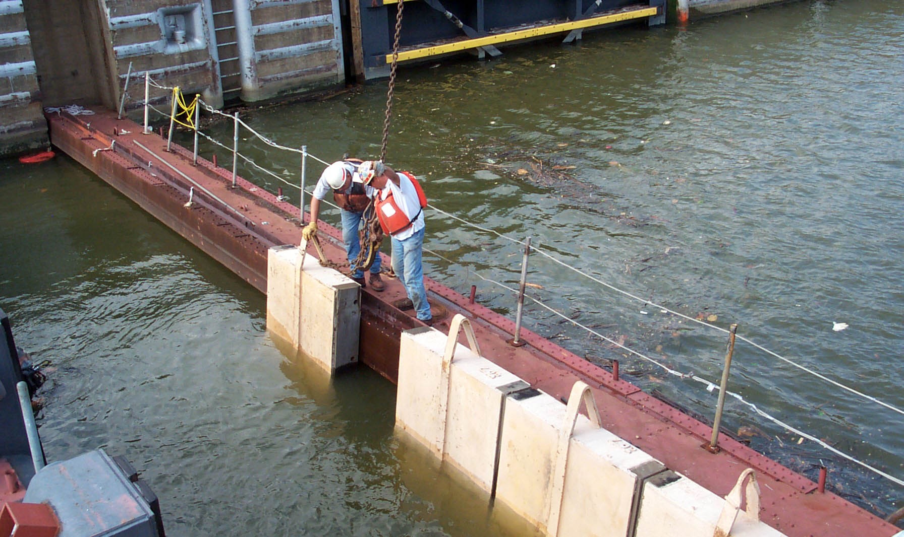
Known as "needle" dams, the barriers are used on the majority of the district's 56-foot lock chambers to hold the river back, so the chamber can be pumped out. The dams consist of 12 steel and timber panels which are installed (nearly) vertically and supported by a horizontal girder (see images on page 2).

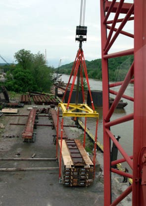
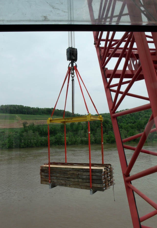
Loading one of these temporary dams usually entails 16 separate crane lifts, one for each needle. This new method pairs lifting saddles (gray beams, underneath) and a spreader (yellow beam on top) above two stacks of the needles, which allows lifting all of the needles at once.

The Structural Design Section did the foundation work to determine how strong of a spreader beam was needed and how heavy the saddles had to be, based on the weight of the dam components. The fabrication and welding work was done by employees of the weld shop at PEWARS. The beam above and the saddles underneath then had to be load tested to 125 percent of the rated capacity.

Each time the lifting device is in use, it consolidates 16 crane lifts into one and saves several hours of labor by several employees.